Pull-up Resistor Circuit Schematic
by AdamStanislav - uploaded on September 27, 2017, 8:46 pm
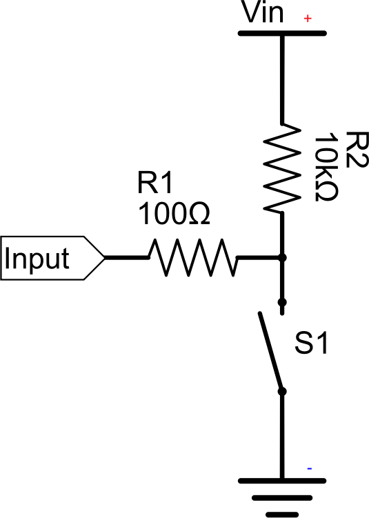
A pull-up resistor works on the same principle as the pull-down resistor from https://openclipart.org/detail/287688/pulldown-resistor-circuit-schematic but the switch S1 is connected to the ground and the R2 resistor to Vin. So, in this case if the switch S1 is closed, electricity takes the path of the least resistance and flows from the Input pin through the 100Ω resistor R1 to the ground, thus interrupting its flow from the positive terminal Vin to the Input pin. But if the switch is open, the electricity flows from the positive terminal Vin to the Input pin through the two resistors R2 and R1. This is the exact opposite of the functionality of a pull-down resistor.
In a pull-down resistor circuit closing the switch starts the flow of electric current between Vin and the Input pin, while in the pull-up resistor circuit closing the switch stops that flow. Both circuit types are commonly used in digital electronics.
Log into OpenClipart
- Tags
- circuit digital electronic electronics Electronics least resistance pull pull-up pullup remix+287688 resistor schematic switch up
- Safe for Work?
- Yes
This clipart is a remix from:
Pull-down Resistor Circuit Schematic
by @AdamStanislav